
Revit Modelling
WORK in PROGRESS
Progress 1


First Floor Plan
Ground Floor Plan

In the first stage when doing Revit modeling, I was trying to form the shape of my concept design with the floor, wall and also the height of each floor without applying any materials. With the circular shape of my design form, i was taking my first attempt to form a curved shape using the sketch staircase. However, it was failed as the opening of the exit from the basement was blocked by the staircase formed. Each of the angle was annotated to ensure all the size of the room was under my control.
Underground Floor Plan
Progress 2
First Floor Plan


Ground Floor Plan

In this stage, I had solved the obstacle forming a staircase that blocking the opening previously. Meanwhile a flip back all the facade surface outward to make the overall building more clean and forming a remove the flooring at the bottom of water fountain by editing the boundary of the floor and replaced it with a glass flooring.
Underground Floor Plan
Progress 3 : First Draft
Roof Floor Plan

First Floor Plan

Ground Floor Plan

Underground Floor Plan


Here was my first draft digital model for my concept design by adding all the materials, roof, door and window and also the railway to make everything work logically. However, in the account of my design is playing with the contour of the site to maintain the original landscaping and existing greeneries of the site, hence there is a problem that I am facing currently, which is forming the contour for my site context. Therefore, I decide to indicate the contour by forming three different height of wall with an surfacing material of sand and earth surface in section. Now I'm looking in how to form the contour in Revit modelling.
Creating Structural System


.jpg)
FIRST Revit Family Creation
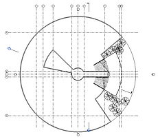
In this first revit family creation, two vernacular architecture element was decided to be created which is double casement louver window and traditional door design. Timber material was applied in the family to make enhance the sense of the old style element, bringing the emotion of experiencer in to the aura of the atmosphere.

STEP 1: Open a new generic model template, to create louver panel. Create reference line and reference plane, annotate and label the annotation as depth and degree.

STEP 2: Create extrusion and applied constrain lock to the reference plane, therefore when the reference line change, the extrusion will change accordingly.

STEP 3: Check all the parameter and name generic file as "Louver".

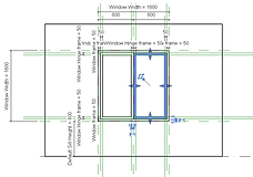
STEP 4: Open a new window family template, create, annotate and label the parameter of the reference line according to the dimension that needed.

STEP 5: Create extrusion as the form of the outer frame for the "Double casement window"

STEP 9: Create a reference line as the thickness of the of the inner window opening panel and align both to the reference line.

STEP 13: Array the Louver and edit to desire number to cove the entire void properly.


STEP 6: Aligned the frame with the wall and apply constraint lock so the thickness of outer frame will same as the thickness of the wall

STEP 10: Load the "Louver" in to the Window Family.

STEP 14: Repeat the step for the other side.


STEP 7: Form another extrusion as the inner frame of the opening panel, according to the reference line created.

STEP 11: Place the louver in to the family file and ready for alignment.

STEP 15: Draw the symbolic line and mirror it to the other side to indicate the direction of the window to open and its degree.
STEP 8: Using mirror (pick axis), to form the second Hinge Frame on other side.

STEP 12: Align the louver to the base of the inner frame and edit its dimension according to inner window panel frame.

STEP 16: Apply materials onto the window, check and load into the project
STEP 17: Place the window family that created into the project.
STEP 18: Check the effect of the window when applied on the wall in the project.
Family 1: Traditional Double Casement Louver Window
Family 2: Vernacular style Shophouse Double Door

STEP 1: Open a new Door Family template and label create al the reference line according to size of door frame thickness and also the offset of 20mm from the ground

STEP 2: Form first extrusion as the first door frame

STEP 2: The middle segment


STEP 3: Join (multiple) all the three segment of inner door frame into one.

STEP 4: Form the cover panel within the inner frame on the top and botton segment

STEP 5: Create reference line and label it as the thickness of the cover panel, and align the cover panel with the reference line as the thickness.
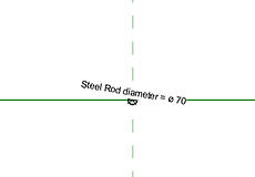
STEP 6: Open an new generic metric template and at the plan, form a circular extrusion as a steel rod that to be applied on the middle segment on the door.

STEP 7: Load in to the Door family template

STEP 11: Mirror all the element of the door to the other side to get an symetrical component on both side using the mirror (pick axis)

STEP 8: Align the rod to the middle segment of the door


STEP 9: Array the rod across the void on the middle segment

STEP 10: Have a quick check on the 3D view to ensure the rod and the panel were fit in to the frame.


Door 13: Draw the sybolic line before load into the project to indicate the direction and the angle of the door to be open

STEP 2: And also the third
STEP 14: Make sure constrain lock were applied on the with of the door.
STEP 12: Double Checking on the door from the 3D view to ensure every element were well aligned and the three geometry segment of the door were well-joined.
STEP 15: The appearance after i apply the materials and load in to the project

STEP 16 Applied into the wall of the Cafeteria to bring a sense of back to the past
REVIT FAMILY CREATION OUTCOME


First Concept Design Outcome
Roof Floor Plan

Ground Floor Plan

Elevation


First Floor Plan

Underground Floor Plan

Sectional View


Room Schedule Creation

Right click on the (Schedules/Quantities) in the menu select "Area Schedule (GIA)" and select the information (Name and Area) needed to form a new room schedule.
Documentation

To complete project documentation, the specified template with specific size need to be load into the project and click "OK" to create a new sheet.
After documentation sheet was created, resize all the autographic drawing into scale 1:200 in order to fit inside the documentation.
Drag the drawing into the sheet and arrange it in clean and in the way that give better understanding.


